I.The outline
Responded to an emergent calling for help from an overseas power plant, at the end of Jun. 2014, with only one week of preparation, Nangang Power overhauling personnel carrying spares and tools rushed to the working field and executed rush repair for fractured air compressor vanes in a set of gas turbine power equipment.
In the accident, the gas turbine tripped and shut down following over vibrations, the compressor vanes were fractured, and the overall circulation part was destroyed. Required by the owner, complete check and overhaul must be executed from the inlet chamber to the end of generator excitation to eliminate the defection, and overall compressor stators and hot gas path parts must be replaced, the newly procured rotors must be replaced with, and the bearing must be replaced.
There were many various problems found out in the working field, for example, the too big clearance between the new rotor and the casing body, discrepancy of the new rotor and loading coupling end, 2mm smaller in bore size for the new bearing, and severe fracture on compressor discharge casing. The processing work required in the working field included polish on the new rotors and stators, processing on coupling and its bearing, mend on fractures, processing on thrust bearing gaskets, etc. The choice of transporting the related parts back to China was not allowed by working schedule time, but in the overseas working field that was limited in working conditions, there were hard problems left to be solved one after another.
Under the efficient support from Nangang Power and comprehensive cooperation from the owner company, the project department of Nangang Power push forward its technical advances, collected wisdom and absorbed useful ideas, making it ensured that every working process was complied with rules and instruction, and winning excellent overhaul result, meeting the owner’s expectation for the turbine set’s operation.
In the next we will retrospect the treatment on partial damages in the gas turbine compressor, and the mend of the factures on compressor discharge casing.
II.Check before overhaul
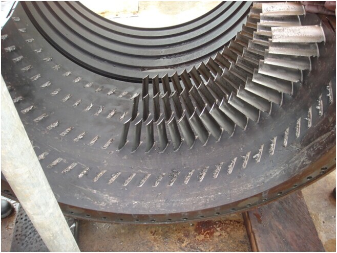
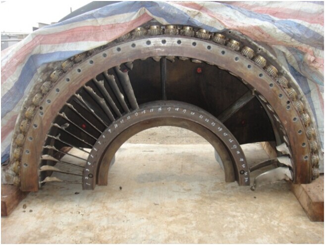
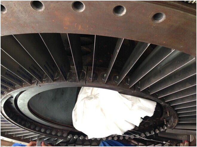
1.In the accident, the gas turbine over vibrated and was shut down, and was checked by entering the man hole gate, finding out the extremely severe fractures on IGV guide vanes and compressor stator vanes.
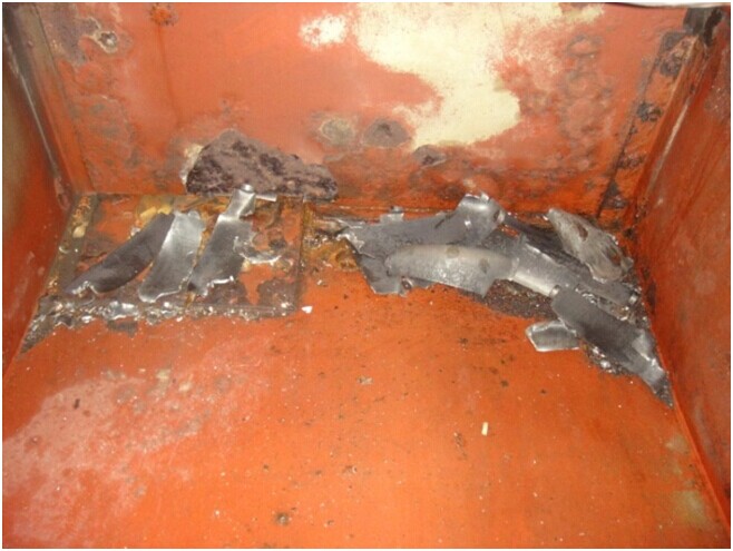
The hit IGV guide vanes falling onto the inlet chamber floor
Broken IGV guide vanes
2.The rotors couldn’t make crank, and getting of the data before overhaul failed, such as:
1)Initial position size of compressor and turbine rotors;
2)Alignment recheck on gas turbine equipment and the auxiliary gearbox;
3)Alignment recheck on gas turbine equipment and loading gearbox;
4)Data measurement of the IGV guide vanes before opening casing.
III.Dismantlement of the power equipment and measurement check:
1.Check:
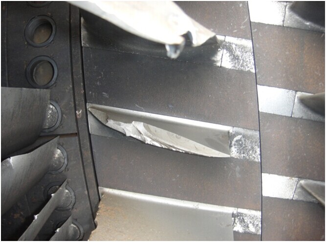
1)Check IGV guide vanes:
All the guide vanes from no.33 to no.48 were hit broken, and the rest hit deformed or twisted.
The hit broken IGV guide vanes
The damaged guide vanes
The broken IGV guide vanes directly impaired the graphite sleeve of the internal air seal ring, leading it to deforming, and the guide vane transmission shaft was hit, leading its orifice mouth to turning bigger and the sleeve inside the orifice to deforming, which made the dismantlement and reinstallation hard in processing. A lot of dents were produced by the hit in the inlet casing, while the silencing board on the right of the inlet chamber was made a hole of 100*30mm by metallic pieces.
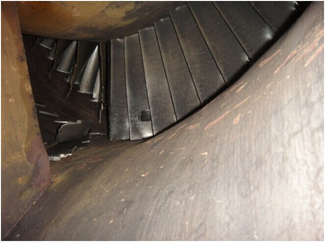
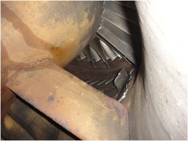
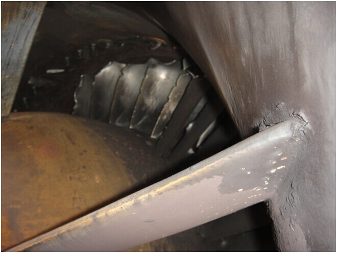
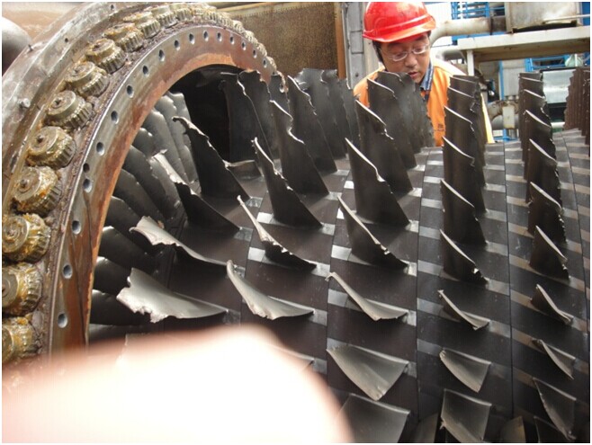
2)Check compressor rotors:
Two vanes of compressor stage 1 rotors were broken from the root, compressor stage 1-4 rotors were hit severely, and compressor 5-17 rotors were damaged seriously.
The broken stage 1 rotors
Damage on compressor rotor vanes
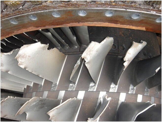
Damage on compressor stage 1 and 2 rotor vanes
3)Measure the height of the compressor rotor vanes, making the comparison for replacing with new rotor.
4)Measure compressor end shaft axle, oil seal baffle and air seal baffle, coupling flange screw holes, and coupling flange seam allowance.
5)Eye inspect compressor disk and pull rod. Eye inspect the compressor disk and pull rod on shaft axle part and the shaft axle.
6)Due to severe damage on compressor rotor vanes, the clearance in the stators and rotors was not measured.
7)Partial inspection on turbine rotor:
A.Clearance measurement in the stators and rotors;
B.Eye inspection on turbine rotors, finding out dents produced by hit of metallic granules;
C.Measurement on turbine end shaft axle, oil and air seal baffles, coupling seam allowance and coupling dowel orifices;
D.Galling on turbine end shaft axle was severe, and the galling on bearing shell was severe.
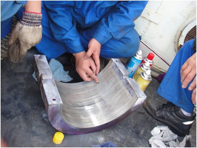
Repair the galling on bearing shell
8)Check the compressor casing and stators:
A.Check air compressor stage 1-17 stators, which were impaired in varied;
B.Measure the height of compressor stators, making the comparison for replacing stators;
C.There were hits and dents on upper and lower casings of the compressor;
D.Clean out and repair compressor casing surface, and make dye flaw detection on compressor casing.
Measure the height of compressor stators before dismantling them
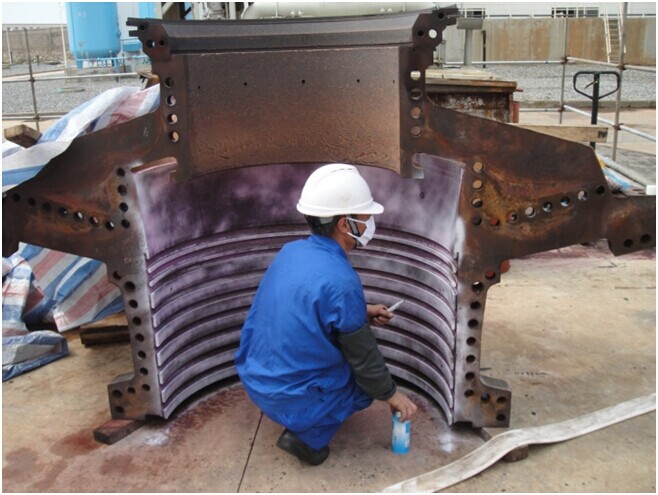
Dye flaw detection on compressor dischargecasing in progress
IV.Measurement for treatment on new and old rotor and stator vanes
Replacement of rotor was decided through research and analysis, and the scheme about replacing all stator vanes:
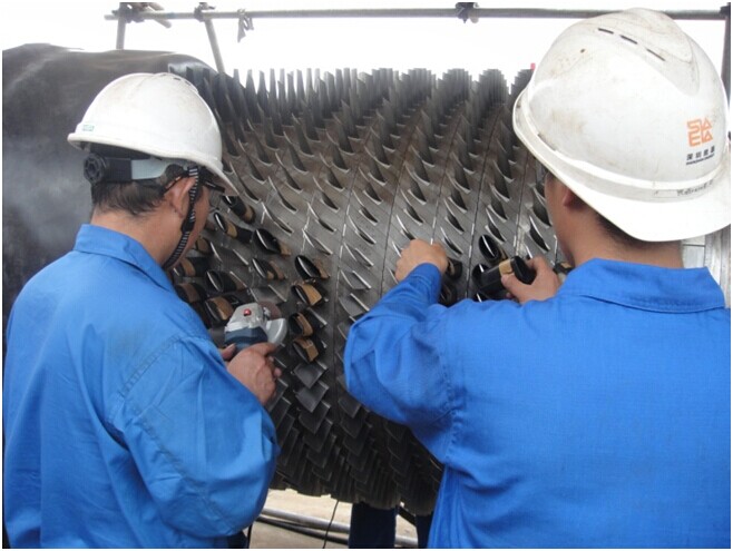
1.Pick up symmetric points on old rotors of compressor 1-17 stage vanes and turbine 1-3 stage vanes, and measure the height;
2.Pick up symmetric points on new rotors of compressor 1-17 stage vanes and turbine 1-3 stage vanes, and measure the height;
3.Pick up six-point positions on old compressor 1-17 stators and EGV1 and EGV2, and measure the height;
4.Pick up six-point positions on the newly replaced compressor 1-17 stage stators and EGV1 and EGV2, and measure the height;
5.Measure the size of the coupling seam allowance of the new and old rotors towards the turbine end;
6.Measure the size of coupling dowel orifice of the new and old rotors towards the turbine end;
7.Measure size of new and old rotors, every axial, oil seal, and air seal baffle;
8.Measure the size of seam allowance towards the new and old compressor end;
9.Test installing the couplings on both ends of the rotor, and check the position of dowel orifice.
The problems appeared:
1.Through measuring and comparing, it’s found out that the new rotor vanes in compressor were shorter than the old ones, and they were different in height;
2.Through measuring and comparing, it’s found out that the compressor stator vanes were different in height too, close to 2mm for the height difference;
3.Unload the new rotor from casing and measure it, knowing the clearance horizontal plane in the compressor rotors and stators was bigger than standard difference, and relied on the measured data from compressor rotors and stators, the value was much lower than the minimal limit of the characteristic;
4.The horizontal clearance of the turbine rotor vanes in casing was bigger too;
5.The seam allowance of the coupling of the new rotor toward the compressor end was 0.03mm bigger than that of the old rotor;
6.The seam allowance of coupling of the new rotor was 0.09mm smaller than that of the old rotor;
7.There were two helicoils-insert incorrectly installed in the connect bolts of the coupling of the new rotor toward the compressor end;
8.On the old balance block of the new rotor, bolts were not punched and riveted;
9.In the stage 3 rotor of the new compressor, the root filling block of a piece of vane was 1.5mm over high.
Treatments:
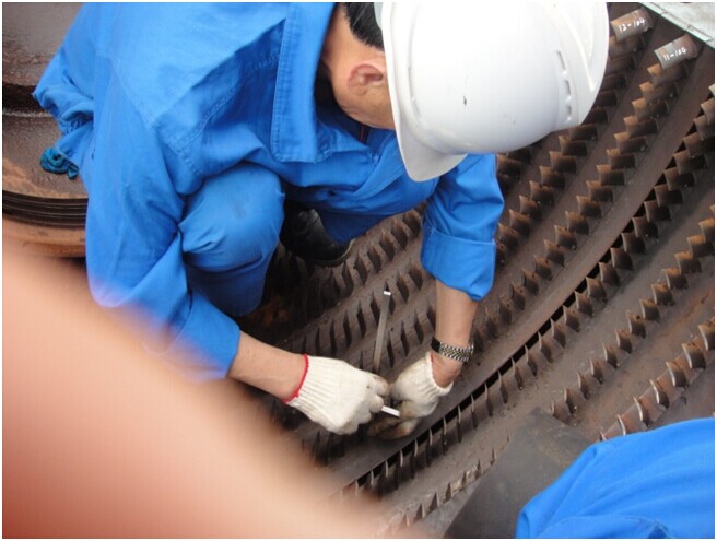
1.Tiny parts of clearance of compressor rotors and stators were, agreed by the owner, mended by polish in the working field;
2.Scale of the polish mend: Compressor stage 6-8 and stage 12-17 rotors and stators, and the mending size was 0.50mm evenly grinded from eachvane with old height;
3.Due to 0.09mm smaller size on rotor seam allowance toward the turbine end, the male seam allowance of the load coupling toward the turbine end was cut 0.09mm by machine processing;
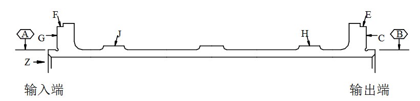
Orientation Z, Face A the input end on the diagram is the processing position for load coupling
Protect the vanes around the compressor when polish mend is executed
The stator vane cut from the stator ring
Gouge stage 1-4 stator ring
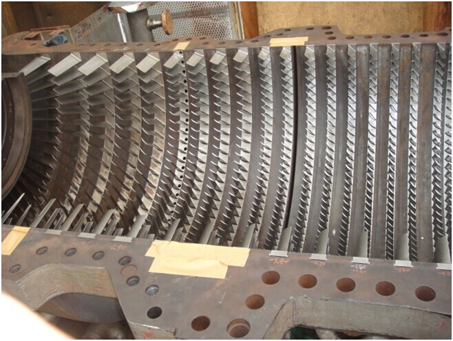
Replace the new compressor stators
V.Replace parts
1.Replace compressor stators:
1)Dismantle the hit broken compressor stage 5-17 stator vanes, EGV1 and EGV2 stator vanes;
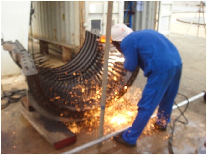
2)Severe corrosion on compressor stage 1-4 stator belts and stator rings, 4 groups in circulation, so it was hard to dismantle;
Negotiating with the owner, by means of carbon arc gouging, we gouged stage 1-4 stator rings, and by two sets of DA welder (400A) which had been parallel connected to augment electricity, all stage 1-4 stator vanes were cut from the vane roots on stator ring, and the stator ring was gougeddivided from the middle section and moved out then;
3)After dismantlement of all stator vanes from upper and lower compressor casings, the surface inside the compressor was polished and mended plane, eliminating the dents and bulges produced by hits;
4)Clean out the surface inside the compressor, the casing and its stator groove; clean the surface of compressor casing, eliminating fouling and oil stain; execute dye flaw detection to check the casing for impairs; defections were not checked out on the compressor casing surface after dye detection;
5)Clean out the surface inside the compressor casing and confirm qualified, and install new compressor stators and IGVs of all stages;
6)Measure compressor stators height of all stages, based on the measuring points on old stator position points.
2.Replace the rotor
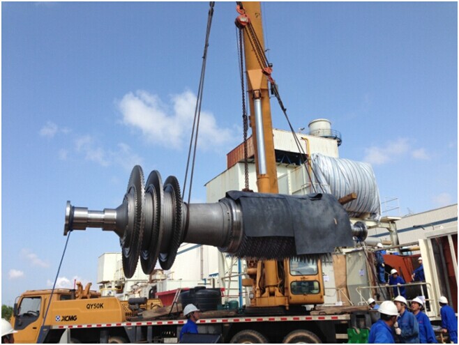
Hoist and install the new rotor
3.Replace IGV guide vanes
Divide the hit broken IGV parts;
Ensure IGV angles by combined casing method.
Damaged upper IGV guide vanes
Assembly IGV guide vanes
VI.Crack mend on upper and lower compressor discharge casings
1.Crack situation
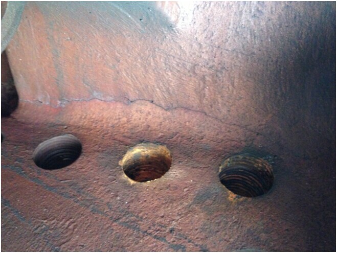
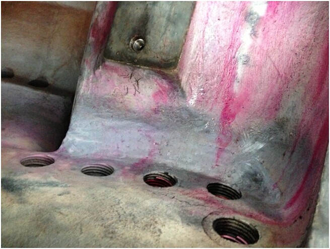
1)Through checking, an irregular breakthrough crack in total length of 218mm was found out at the arc turning corner of a casting in right side beneath the horizontal joint in lower compressor discharge casing. See below photo:
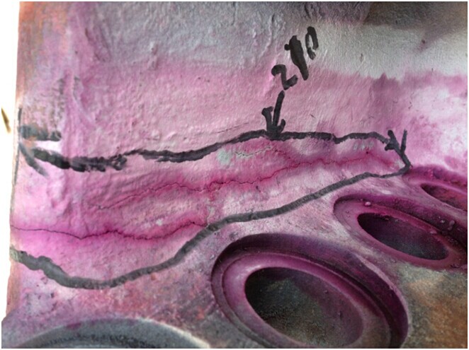
2)Via PT nondestructive testing, an irregular breakthrough crack 30mm to the end shaped in reversed V and in length of 70mm and the total length 210mm,was found at the arc turning corner of a casting in left side above the horizontal joint in upper compressor discharge casing. See below photo:
3)Via PT nondestructive testing, there were 26 no breakthrough cracks varied in the length of 30-60mm found out on upper and lower compressor discharge casings.
2.Analysis on why the cracks appeared
In long time operation of the compressor discharge casing and affected by working conditions, the carbon element in castings would form thick and long graphite substance laid out in the shape of flake, so the major reasons of producing cracks were the segregation of the chemical compositions on the castings, thick and big crystal granules on the structure of the castings, etc.
3.Mend the cracks by cold weld
1)The material of the compressor discharge casing: ASTM A536-93 65-45-12; thickness of the casing in the welded area: 12-35mm more or less;
2)Execute careful check to confirm the about-to-weld areas and the start and end points of the cracks; execute crack arrest measures on the prolonged lines of the start and end points of the crack; execute the measures to decrease weld stress on various points on a section of crack;
3)Based on comprehensive consideration about stress, deformation, operation difficulty, weldment thickness, welding position, welding rod diameter etc., prepare reasonable welding groove correspondingly; in the process, the metals close to cracks were shoveled clear, and the galling, impurity substances and oxidized skin were cleaned out from welding grooves and their end, so as to make sure the polished metal appeared and avoid welded sections in the casing from heat impact; make double faced welding grooves shaped in X, symmetric in double face, and execute welding;
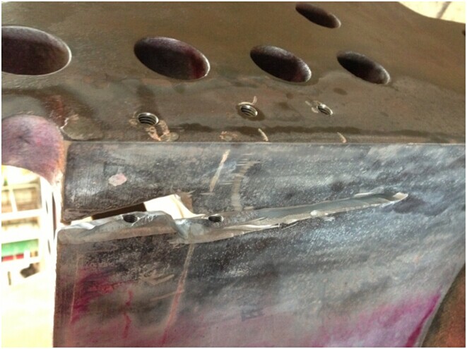
4)In order to make sure excellent solder of solder metal and the casing, and decrease the phenomena of white cast and cracks in solder seams and melting areas, enhance overall strength of solder metal and welding areas on the casing, and increase welding effect, the method of inserting screws into divided sections in the solder seams. There were extremely high requests on the size, number, length, and clearance of the inserted screws. Asection inserted with screws in upper compressor casing can be seen in the below photo:
5)The weld was executed strictly complied with instructions and requirements of cold weld method, so during the solder process, the heat-input output by solder was controlled to decrease heat stress zone. The interbedded temperature of welding was controlled below 45 degrees centigrade, and there were strict requests on length & thickness of solder seam in the usage of short arc weld and short seam weld. Sway of the arc was not allowed during weld, and after soldering one section or one bed, when the solder seam was in red hot state, hammer the seam by pneumatic chipping hammer until the seam turned dark, and then grind the seam to relax stress and block the air blowholes and meantime, thinning the crystal granules in weld section. Clean out interbed, and execute PT nondestructive testing on the inter-beds; once defection was found out, clear it out and proceed on next solder.
4.Check the weld
1)Before weld, execute PT nondestructive testing on the welding groove face and the area with 30mm of radius around it;
2)Execute nondestructive testing in inter-beds of the weld, and confirm qualified;
3)Execute nondestructive testing 24-hour after welding process on upper and lower compressor discharge casings, and confirm qualified;
5.Photo of the compressor discharge casing after mending cracks:
6.Check the planeness of the horizontal joint in compressor discharge casing
After the welding process, execute check and comparison for the planeness of the flange faces in upper and lower compressor discharge casings before and after the welding process respectively, resulting the max welding shrinkage: 0.01mm, not affecting on normal operation of the gas turbine set.
7.Other treatments on small cracks
1)Through PT nondestructive testing, a breakthrough crack in the length of 35mm and 30mm to the end was found out at the circle turning corner of a casting in the right rear end above the horizontal joint in upper compressor discharge casing, and preventive measures were executed at the working field to stop the crack extending;
2)Through PT nondestructive testing, there were 28 non-breakthrough cracks varied in the length of 20-65mm on studs and two ends of the vertical flange in upper compressor discharge casing, and preventive measures were executed at the working field to stop the cracks extending.
VII.Put the turbine set into service
Required by the country’s needs for power supply, the mission was completed within toughly demanding overhaul guarantee schedule set by the owner. After putting the gas turbine set into service, parameters of all items were in excellent targets, among which, the turbine vibration was below 4mm/s.
The overhaul time and difficulty, and target indexes of all items were greater than the owner’s expectation. And thus, Nangang Power won favorable comment from the leaders and operative departments in the owner company: professional maker’s level, rich overhaul experiences, dedicated spirit of thinking of everything for the customers, and our confirmed good partner, otherwise such an overhaul was hard to think of.
Finally, the damaged equipment was revived, and the good comment from the owner made us much delighted, which was the result we were looking forward to, and the thrust force making us continue to endeavor.
Photographer: Li Furang